By John Castle, Electronics and EMC Specialist at RGH Converting.
Published 28 July 2026 · Last updated 9 September 2026
EMI shielding is the practice of blocking, redirecting or absorbing electromagnetic interference (EMI), also called radio frequency interference (RFI), so it cannot degrade the performance of nearby electronics.
In an enclosure, that job usually falls to conductive gaskets, tapes and absorbers that close the gaps electromagnetic energy leaks through. When interference rises against signal strength, the signal-to-noise ratio falls, and the symptoms follow: data errors, incorrect sensor readings, failed compliance tests, even temporary shutdowns.
This guide compares the five main shielding material families, explains the selection criteria that actually decide performance, and covers how die-cut EMC gaskets and conductive tape parts arrive at your line ready to place. It draws on the 3M™ EMI/RFI Management Solutions range that we convert and supply as a 3M™ Preferred Converter.
What an EMI shielding gasket actually does
A metal enclosure only works as a shield if it is electrically continuous. Every seam, lid, panel joint, display aperture and cable entry is a slot that lets electromagnetic energy in or out, and the higher the frequency, the smaller the gap that matters. An EMI shielding gasket restores continuity across those joints: a compressible, conductive part that grounds a lid to a chassis, seals a display wrap, or bonds a shield can to a PCB. The same materials handle three related jobs: shielding (closing leak paths), grounding (low-resistance connection between surfaces) and electrostatic discharge control.
The five EMI shielding material families compared
Representative data from the 3M EMI/RFI Management Solutions portfolio. Values are typical, not for specification; confirm against the product datasheet.
| Family | Construction | Thickness | Best for | Example 3M grades |
|---|---|---|---|---|
| Conductive foam gaskets | Metal-plated open-cell PU foam with conductive adhesive | 0.33–0.75 mm | Grounding across wide or uneven gaps; compressible and reworkable | ECG7000H, ECG8000H |
| Fabric-over-foam gaskets | Conductive-fabric-laminated foam, internal copper layer available | 0.3–3.0 mm | Very wide gaps needing high compression with reliable grounding | MSG7000 SDX |
| Electrically conductive tapes | Fabric, foil or transfer adhesive with conductive fillers; XYZ or Z-axis | 0.03–0.13 mm | PCB, flex and chassis grounding; shield-can attachment; bond-line shielding | 5113DFT, 9772, 9703 |
| EMI absorbers | Magnetic-particle composite sheet with acrylic adhesive | 0.05–1.0 mm | Absorbing noise at the source; 100 MHz to 6 GHz by series; antenna performance | AB5000, AB7000, AB1000, EM25TP |
| Magnetic shielding foil | Nanocrystalline soft magnetic foil, permeability to ~80,000 | 0.05 mm | Low-frequency magnetic fields below ~20 MHz; NFC and wireless charging | EM80KM |
Thicknesses are typical ranges across each series. Refer to the individual product datasheet for tolerances and full test conditions.
Choosing between families is usually straightforward once you know where the problem sits. A physical gap that needs conductive sealing takes a foam or fabric-over-foam gasket. A flat joint, flex circuit or shield can take a conductive tape. Noise radiating from a chip, trace or cable is a job for an absorber placed at the source. And interference below roughly 20 MHz is magnetic rather than electric, which is why it ignores ordinary conductive shields and needs high-permeability foil instead.
Where shielding problems show up
The same handful of locations account for most EMI work in practice. Shield-can lids and their attachment to the PCB. Display wraps and the chip-on-flex behind them. Camera module and sensor grounding, where a small conductive part quiets an intermittent fault. Flex-to-PCB interconnections and chassis grounding points. Cable entries and wrapping, where noise rides in and out of an otherwise clean enclosure. And in RF products, PIM management and antenna regions, where an absorber in the right place recovers performance that no amount of grounding will. If your failing frequency and the physical location are known, the material family usually picks itself from the table above.
Selection criteria that decide performance
- Frequency range. Absorber performance is thickness- and series-dependent (the AB1000 series targets 2 to 6 GHz; AB7000HF covers 500 MHz to 4 GHz), and bond-line gap shielding matters most at higher frequencies where small slots radiate. Match the material's target band to your emission scan, not to a generic claim.
- Gap size and compression. Foam gaskets ground under compression, so thickness selection against the real tolerance stack decides whether contact is maintained. Wide or uneven gaps push you towards fabric-over-foam.
- Contact resistance and conduction path. Z-axis-only products (like 9703 transfer tape) conduct through the bond line; XYZ products (5113DFT, 9772) also conduct across it. The 9772 series holds XY resistance around 0.015 ohms, which is why it is a go-to for grounding.
- Adhesion and substrate. Peel strength varies with surface energy and assembly pressure; low-surface-energy plastics need grades specified for LSE. Contact area on small grounding pads is often the binding constraint.
- Environment. Operating temperature ranges differ widely (5113DFT is rated for long-term use to 105°C; some absorber and foil options reach 150°C), and dissimilar-metal contact invites galvanic corrosion in humid environments, so check the plating against the mating surface.
- Rework and handling. Conductive foam gaskets are reworkable during assembly; double-coated tapes are easier to die-cut and handle than carrier-free transfer tapes. If your line needs repositioning tolerance, decide this first.
Die-cutting conductive materials: what changes
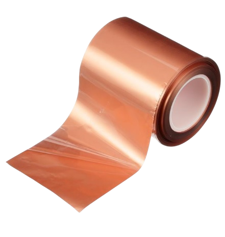
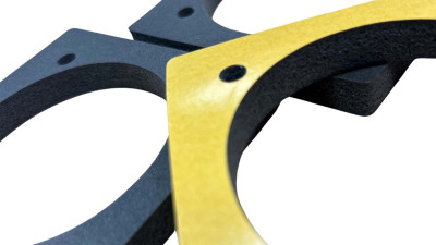
Conductive constructions behave differently on cutting tools than standard PSA tapes. Fabric carriers can fray at the edge if the tooling is wrong, foil layers hold a cut edge but mark easily, and metal-plated foams need cutting pressure that seals the gasket edge without crushing the cell structure that makes them compressible. 3M grades differ in how forgiving they are: the 9713 nonwoven construction, for example, is specified for its die-cutting and converting behaviour, and the gasket tapes ship on removable liners specifically to ease die-cutting and small-part handling.
RGH converts and slits 3M electrically conductive tapes and supplies EMC parts as die-cut gaskets, kiss-cut pieces on a continuous liner, or slit rolls. As with every delicate construction we handle, we discuss and trial the format and liner with you before production: the right presentation decides how cleanly small conductive parts release and how fast they can be placed, by hand or by feeder. Rotary and flat-bed die-cutting cover complex geometries, apertures and registration features. If you aren't sure which 3M tape is for you, check out which 3M VHB grade to choose in our latest article.
Thermal management often sits alongside shielding in the same enclosure. If you are also managing heat, our thermal tape selection guide covers the material trade-offs on that side, and our foam gasket buyer's guide does the same for environmental sealing.
A note on EMC compliance
Shielding materials are one tool for passing the emissions and immunity testing behind CE and UKCA marking under the EMC regulations, alongside layout, filtering and cable management. A gasket will not rescue a fundamentally noisy design, but it is frequently the difference between a marginal fail and a pass at the test house, and it is one of the few fixes that can be retrofitted late in development without a board respin. This is general guidance rather than compliance advice: your test results govern.
Frequently Asked Questions
EMI Shielding FAQs
-
What is EMI shielding?
EMI shielding is the use of conductive or magnetic materials to block, redirect or absorb electromagnetic interference so it cannot disrupt electronic circuits. In practice it means conductive gaskets, tapes, absorbers and coatings applied to enclosures, joints and components.
-
How does EMI shielding work?
Conductive shields work like a Faraday cage: incident electromagnetic energy induces currents in the conductive surface, which reflect and dissipate it instead of letting it reach the circuit. Absorbers work differently, converting electromagnetic energy to heat in magnetic particles. Effectiveness depends on conductivity, coverage and, above all, the continuity of the shield at seams and gaps.
-
What is the difference between EMI and RFI?
RFI is a subset of EMI. EMI covers all electromagnetic disturbance, from low-frequency magnetic fields to microwave-band noise; RFI refers specifically to interference in the radio frequency range. In shielding practice the terms are used almost interchangeably, which is why materials are usually badged EMI/RFI.
-
Why is EMI shielding important?
Unshielded interference degrades the signal-to-noise ratio in electronic systems, causing data errors, sensor misreads and intermittent faults, and it can push a product over the legal emissions limits it must meet for CE or UKCA marking. As devices get denser and switching frequencies climb, shielding is now designed in rather than retrofitted.
-
How do you use EMI shielding tape?
Clean both surfaces, apply the tape or die-cut part across the joint or onto the grounding point, and apply firm pressure so the conductive adhesive makes contact. For repeatable results in production, tapes are usually supplied as die-cut or kiss-cut parts sized to the joint rather than cut from a roll by hand.
-
Does aluminium foil shield EMI?
Conductive metals like aluminium do reflect electric-field EMI, which is why foil tapes exist. But household foil has no conductive adhesive, cannot maintain grounding contact across joints, and does almost nothing against low-frequency magnetic fields. Engineered shielding tapes and gaskets solve the contact and continuity problems that determine real-world performance.
Get the 3M EMI/RFI guide, or trial parts on your enclosure
Download the full 3M EMI/RFI Management Solutions brochure, or send us your enclosure drawing and problem frequency range. Our technical team will recommend a material family and grade, then supply trial parts in the format your assembly needs.
Request Die-Cut Samples
Test the fit before you commit. Samples cut to your drawing.